请输入正确的账号名!
密码格式有误请验证!
请输入正确的账号名!
请输入正确的账号名!
请输入正确的单位名称!
请输入....!
请输入....!
请输入....!
请输入....!
请输入....!
目前您的账号暂时还不能进行登录哦~
对此我们深感抱歉!但还请您耐心等待审核通过
注册信息审核通过后我们将会在第一时间以邮件的方式通知您
请输入正确的账号名!
请输入....
请输入....!
请输入....!
请输入....!
密码格式有误请验证!
密码格式有误请验证!
请输入....!

AIFEM is intelligent software that is independently developed by Nanjing Tianfu Software Co., Ltd for full-process finite element analysis (FEA). During software requirement analysis, AIFEM developers integrate industrial intelligence, digital twins, and data driving technologies to implement digital product models based on numerical simulation calculation, parameter sensitivity analysis, and numerical experiment databases.
AIFEM facilitates engineering application in the following aspects: The model repair and automatic meshing features of AIFEM minimize the pre-processing workload of engineers, and the support for abundant element types and material constitutive equations facilitates computing and analysis in the solid mechanics, structural mechanics, heat transfer, and electromagnetics fields. Moreover, AIFEM can compute flutter, gust response, and static aeroelasticity during multiphysics coupling analysis. AIFEM helps industrial enterprises establish an integrated design, simulation, and optimization process and improve product R&D efficiency.
CHARACTERISTICS
(1) AIFEM provides both universal features that apply to multiple fields and custom features that are tailored to specialized branches. AIFEM reduces technical requirements and offers simplified and efficient simulation analysis and design optimization tools to run actual projects.
(2) AIFEM collects and generalizes practical and instructive analytical solutions, a large amount of public trial data, and widely recognized reliable numerical analysis data. AIFEM also fully validates the solver. These measures ensure that users have a quantitative and thorough understanding and control of data accuracy and reliability.
(3) AIFEM developers conduct in-depth surveys on the requirements and habits of engineers to optimize the usage process, database storage, and data statistics and analysis and reduce repetitive work as much as possible.
HIGHLIGHTS
(1) Clear simulation process
AIFEM provides a complete and clear simulation process from geometric model import, meshing, and solution setup to post-processing and visualization. The entire process is completed on one GUI without frequent page switching. Solution setup is tailored based on the working habits of design and simulation engineers. This way, engineers can smoothly define material attributes, cross section attributes, analysis types, load, and boundary conditions, formulate computing solutions, and monitor the computing process in AIFEM. Users need only to set the required parameters. AIFEM automatically proceeds with all the subsequent simulation operations. This process makes AIFEM friendly to design and simulation engineers.
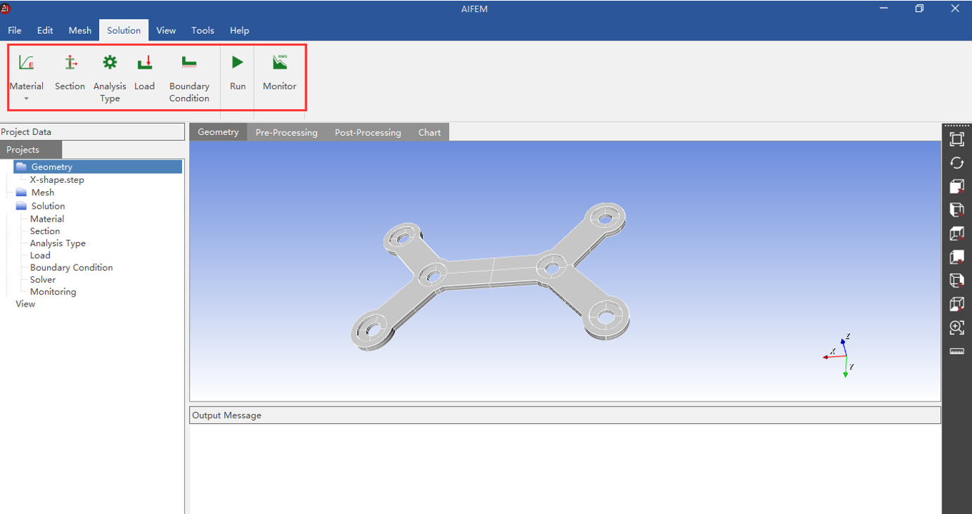
Figure 1 Clear simulation process
(2) Abundant FEA features
AIFEM provides common FEA features in industrial design and engineering simulation, including static force analysis, inertia relief, modal analysis, buckling analysis, harmonic response analysis, elastic-plastic analysis, and transient analysis (including time domain analysis and mode analysis).
AIFEM also provides thermal analysis features, such as steady-state heat transfer analysis (including linear and nonlinear analyses), steady-state thermal radiation analysis, and transient linear heat transfer analysis. In addition, AIFEM can compute flutter, gust response, static aeroelasticity, and aerothermoelasticity during multiphysics coupling analysis. AIFEM also provides computational electromagnetics (CEM) features based on simple optical methods and the initial method of moments (MoM).

Figure 2 Abundant FEA features
AIFEM allows you to import various formats of existing 3D models on the market and also finite element models that are already meshed by other commercial software. This facilitates refined simulation and eliminates the issues caused by subsequent mesh distortion.
During automatic meshing, AIFEM adjusts the mesh density based on the curvature and minimum geometrical dimensions. In addition, AIFEM supports mesh quality checks. For example, you can check the aspect ratio, warpage, collapse ratio, and minimum edge.
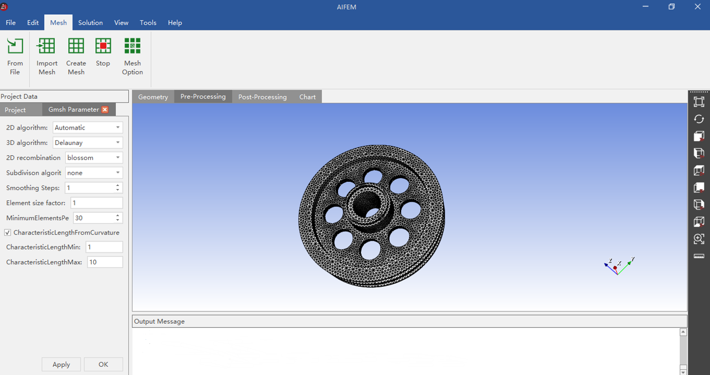
Figure 3 Powerful meshing features
AIFEM has comprehensive pre-processing and post-processing features. The pre-processing module supports meshing, load application, solution setup, and the custom definition of the analysis type, cross section attributes, material attributes, contact attributes, and boundary conditions. You can save the materials that you create to the material library. This allows you to customize your own material library. The post-processing module provides abundant visualization features, such as nephograms, charts, and result comparison.
(3) Quick and intelligent FEA and real-time simulation
Other commercial FEA software requires a long time for simulation. AIFEM uses AI technologies to accelerate FEA computing, which dramatically improves FEA efficiency. AIFEM deeply integrates FEA and AI technologies to implement real-time simulation for specific analysis types. The quick and intelligent FEA and real-time simulation features make AIFEM a good choice for design engineers in routine simulation work.
(4) Versatility and scalability
AIFEM can be used in various industrial fields, such as aeronautics and aerospace, maritime, energy and power, and automobile industries. The script language embedded in AIFEM allows you to further develop and customize the software, thereby ensuring high scalability.
(5) User-friendly GUI and adaptation to multiple operating systems
AIFEM provides a client-based GUI and supports parallel CPUs to meet complex and heavyweight FEA requirements. Both Windows and Linux versions of AIFEM are available.
ACCURACY VERIFICATION
(1) Static force analysis of delta wings
X indicates the spanwise direction, Y indicates the flow direction, and Z indicates the wing thickness direction. Given that delta wings are symmetric in the X and Z axes, only a quarter geometric model is established.
Quadrilateral and triangle shell elements are used for the skin and the leading edge, respectively. Quadrilateral shell elements under shear stress are used for the spar and rib, and link elements are used for the intersection of the spar and rib. (* The following line chart on the left shows the concentrated load at the leading edge, whereas the line chart on the right shows the concentrated load at the trailing edge.)

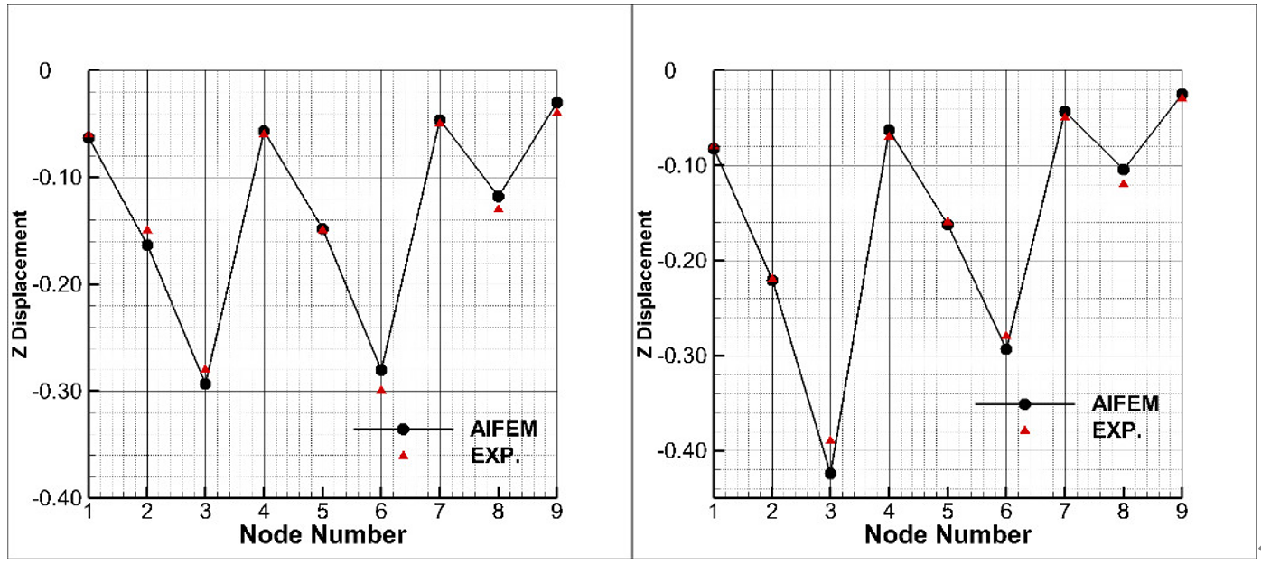
Figure 4 Comparison between the computational result of AIFEM and experimental data
(2) Static force analysis of 3D solid models
The finite element model of AIFEM is as follows:
The dimension of the 3D rectangular solid model is (L, W, H) = (20, 4, 16). The torque applied to one end of the rectangle is My = 2.048e3. Other edges are fixed. Hexahedral elements are used. The following line charts show the comparison between the computational result obtained by using AIFEM and the theoretical analysis data. Theoretical analysis methods are used to calculate the displacement of each node and the stress at the element center. The stress value calculated by using AIFEM is the average stress value of all elements.

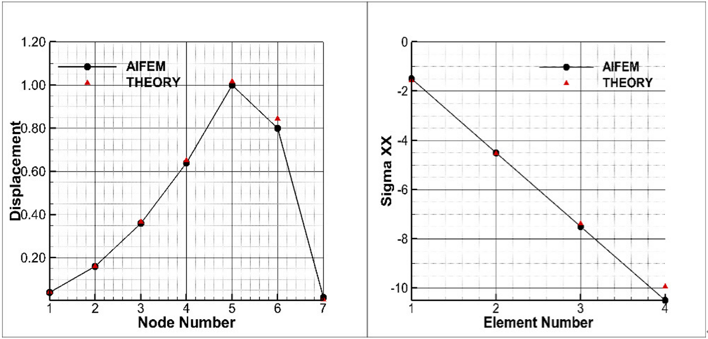
Figure 5 Comparison between the computational result of AIFEM and theoretical analysis data
(3) Modal analysis
The finite element model of AIFEM is as follows:
The dimension of the 3D flat plate model is (L, W, H) = (20, 20, 1). The hinge connection is used for the four edges. The elastic modulus is 3.0e7. Poisson's ratio is 0.3. Quad elements are used.

Figure 6 Results computed by AIFEM for the first to third mode shapes
The following table compares the theoretical analysis data and the results computed by AIFEM using a coarse mesh and a fine mesh, in terms of the vibration frequency of the first, second, and third mode shapes.

(4) Buckling analysis
The finite element model of AIFEM is as follows:
The geometry is a cylindrical surface. The dimension of the cylinder is (R, H, T) = (80, 50, 2.5). No axial displacement exists at the two edges in the height direction. Triangular elements in the cylindrical coordinate system are used.
The following figure shows the computational result obtained by using AIFEM.
Eigenvalue analysis is performed to obtain the eigenvalue and eigenvector of the first four modes. The following figure shows the shapes of the first three modes.

The critical load of each mode is calculated separately. The following figure compares the critical load in the first four modes calculated by AIFEM and the theoretical analysis data.
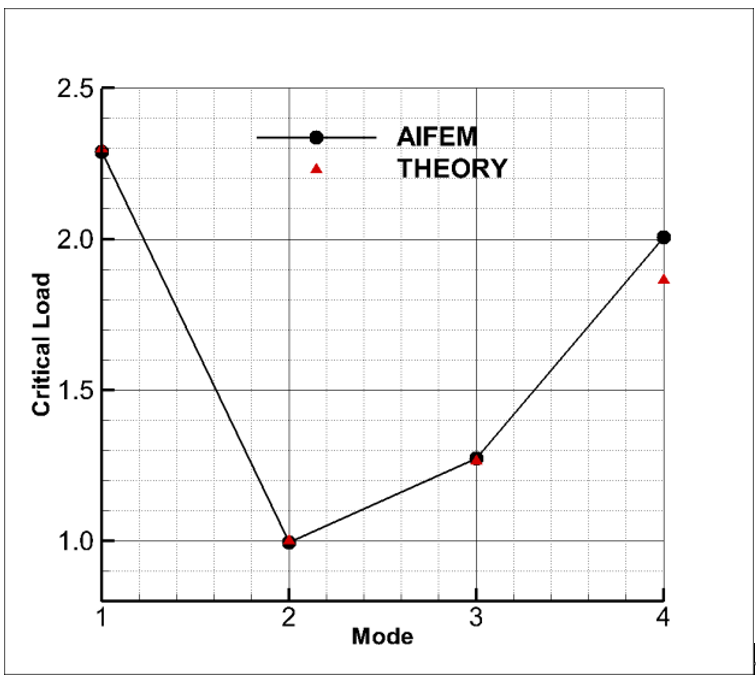
Figure 7 Comparison between the computational result of AIFEM and theoretical analysis data
(5) Harmonic response analysis of a propeller
The finite element model of AIFEM is as follows:
A simplified propeller blade model is built based on the geometries of the middle surfaces of the blade and disc. The frequency of the unsteady aerodynamic load is 133.3 Hz. Triangular elements in the cylindrical coordinate system are used.
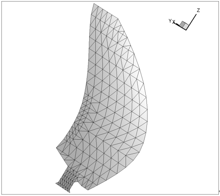
Figure 8 AIFEM mesh
Feature analysis is performed to calculate the 18 modes of the propeller blades. The response of propeller blades to unsteady aerodynamic load is calculated based on the mode computational result. The following figure shows the deformation displacement of the propeller blade and the normal stress distribution nephogram.
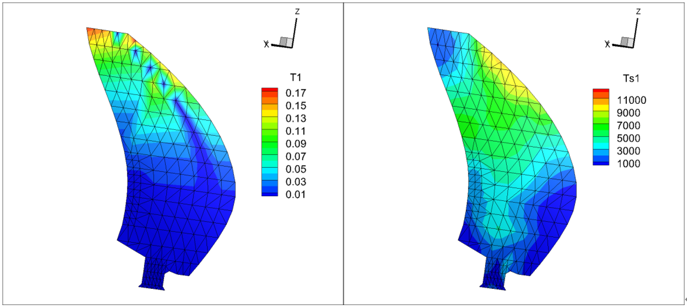
Figure 9 Computational result of AIFEM
CASES
(1) Static force analysis of a spiral case
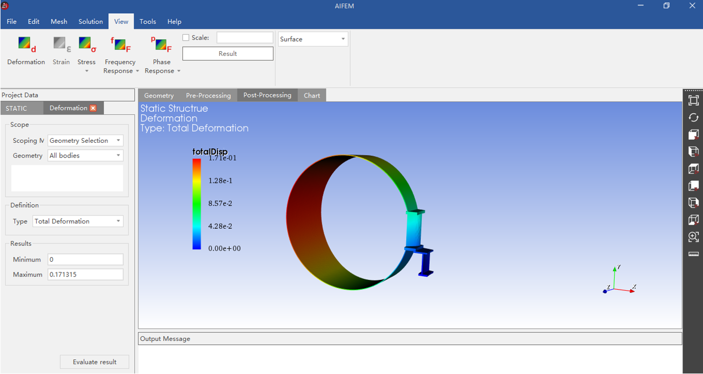
Figure 10 Displacement nephogram obtained from the static force analysis of a spiral case
(2) Simulation analysis of a fan
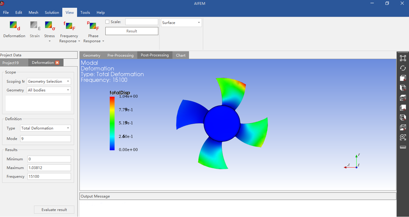
Figure 11 Displacement nephogram obtained from the simulation analysis of a fan
(3) Harmonic response analysis of an amplitude transformer
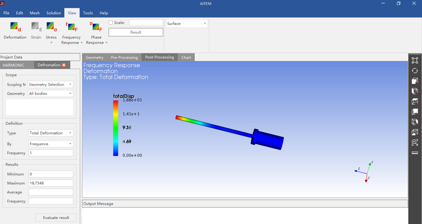
Figure 12 Displacement nephogram obtained from the harmonic response analysis of an amplitude transformer
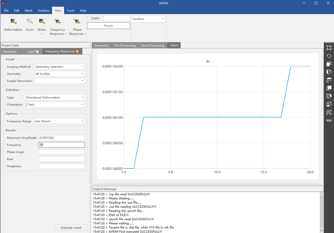
Figure 13 Displacement-frequency diagram obtained from the harmonic response analysis of an amplitude transformer
(4) Buckling analysis of a ring-pull can
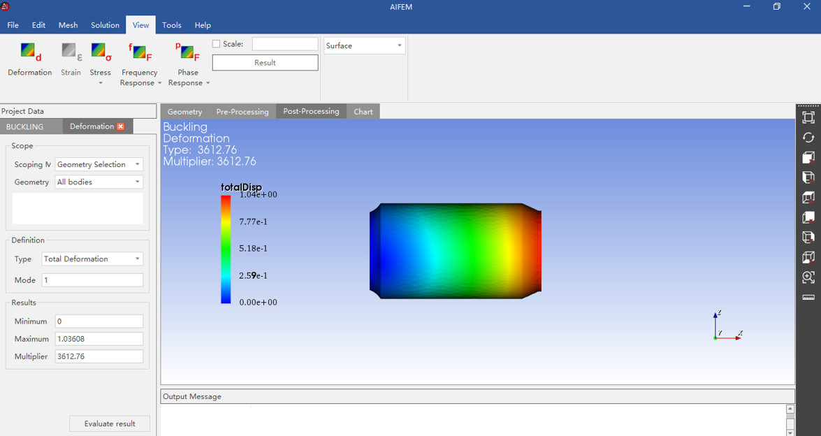
Figure 14 Displacement nephogram obtained from the buckling analysis of a ring-pull can
The current version of AIFEM provides various features, such as static force analysis, modal analysis, harmonic response analysis, buckling analysis, thermal analysis, spectral analysis, random vibration analysis, and intelligent acceleration. The electromagnetic computing and multiphysics coupling analysis features will be launched soon.
For more information, see the latest updates on the official website of Nanjing Tianfu Software Co., Ltd.
